")
")
")
")
")
")
")


")


Description
RWC Refrigerator Cabinet Line
PRODUCT TYPE
• Cabinet
• Models: 16′, 18′, 19′, and 20′
EQUIPMENT TOOLED SIZES
• Height: 64.960 and 70.859
• Width: 27.796, 29.763, and 32.626
• Depth: 23.254, 25.173, and 26.823
EQUIPMENT RANGES
• Height: 59.06 to 76.77
• Width: 23.62 to 37.40
• Depth: 21.65 to 37.40
EQUIPMENT DESCRIPTION
This equipment will consist of the following:
• DE-STACKER: 4-position de-stacker with two (2) stacks on each side of exit/launch conveyor. Blanks are loaded on a pallet. Pallet is loaded onto a roller conveyor (supplied by RWC) and transferred into de-stack position. The top blank from each stack will be removed and transferred to launch conveyor via a servo operated linear pick and place transfer.
• NOTCH AND PIERCE: Wrapper Notch and Pierce Station to notch blanks for each model. The C-frames will be hydraulic cylinder actuated with self-contained die sets. The system will operate at 2000 PSI. Ten (10) self-contained die sets are included. Model select is automatic for tooled sizes. Ranges have capability of reaching minimum/maximum dimensions and are servo controlled. The blank enters from de-stacker. The blank is crowded and squared. The dies advance at the same time and retract. The blank is conveyed out of station to turnover. Scrap conveyors are supplied to remove scrap and locate in one (1) common place.
• ROLLOVER: The wrapper is transferred into station and clamped. The wrapper is rolled over 180 degrees bringing painted side down. The wrapper is transferred to launcher for roll mill.
• LAUNCHER AND ROLL MILL: Wrapper launcher will be supplied to locate blank from notched corners, grip blank both leading and trailing, and guide blank into and through roll mill. The sheet will be driven via servo motors. The roll mill will be supplied with rolls designed for new product flanges. The transfer system will be two (2) dual grip and pull transfers in order to meet cycle time. The transfers will be linear module servo driven with automatic changeover on trailing end for blank length. The roll mill will form front flange with the exception of final 90 degree bend. The rear flange will be completely formed in roll mill with any material variation going toward rear flange.
• FINAL 90 DEGREE BEND: The final bend on front of wrapper will be the 90 degree bend. The wrapper will come out of roll mill into this station. The wrapper is squared and crowded into bender. The final 90 degree bend is made on front flange only.
• TOE FOLD AND FLUSH CORNERS: Wrapper toe fold will be supplied with end bend tooling in order to fold toe flanges of wrapper 90 degrees. On front side of flange are two (2) hydraulic units to form corners for flush corner design.
• LOAD AND CLINCH NUT PLATE RIGHT AND LEFT HAND: Wrapper is transferred into station and located off leading corner notch. The wrapper is squared, a right and left hand nut plate are fed from two (2) bowl feeders and placed in location onto wrapper and held. Two (2) clinch units transfer in and clinch brackets to wrapper in two (2) places.
• TWO (2) IDLE STATION CONVEYORS: After Toe Fold Station will be two (2) idle station dual strand conveyors 17′ in length to be used for additional stations for future needs.
• 40-PART ACCUMULATION (EACH SIDE) STACKER CONVEYOR: Wrapper is conveyed into station between RH and LH accumulating towers. The wrapper is conveyed perpendicular to LH accumulator elevator. The wrapper is either passed through or elevated to one (1) of eight (8) stack positions depending on product model being manufactured. The next wrapper is conveyed perpendicular to RH accumulator and is either passed through or elevated to one (1) of eight (8) stack positions depending on product model being manufactured. At each end of accumulator are elevators to either elevate a wrapper or lower a wrapper from accumulator and transfer it to a launch conveyor to U-Fold Station.
• TWO (2) VERTICAL U-FOLD STATIONS: This will be a Vertical U-Fold Station. The wrapper is conveyed into station. The wrapper is transferred in liner and into u-folder where it is located from leading corner notch. The wrapper is clamped and bend wings extend and form sides up 90 degrees. The unload robot grips panel and removes it from u-folder.
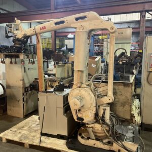
• AUTO UNLOAD: Two (2) Kuka robots with end effectors (EOAT) and vacuum cup assemblies that will grip sides of cabinet and remove it from U-Fold Station and rotate it 90 degrees and set it down on its back onto a conveyor.
• HYDRAULICS (LOCATED AT OPERATIONS 20, 60, AND 80): There will be three (3) hydraulic power units operating at a range of 2000 psi with adequately sized reservoir, motor, pump, heat exchanger (if required), and associated equipment all mounted in a 3O deep spill pan. Located at Stations 20, 60, and 80.
• SEQUENCE CONTROLS FOR ALL OPERATIONS: The above operations are operating as an automatic system and will be controlled with one (1) Allen-Bradley ControlLogix processor with sufficient memory and I/O capacity, control transformer, control relays, and fuses all enclosed in an air-conditioned NEMA 12 enclosure and four (4) operator interface terminals, i.e., PanelView Plus 1000 touch screen with Ethernet, will be provided for operating machines in manual or automatic and diagnostic purposes.
• SYSTEM GUARDING: One (1) lot of system guarding will be provided, including floor mounted lexan panels mounted along sides of Cabinet Fabrication Line. Gate guard switches will be provided on hinged guards where access to inside of line is required which, when opened, will drop power to equipment.
• LEXAN SOUND ENCLOSURES OVER HPU’S: RWC to provide sound enclosures over HPU’s to get to an 80 dB(A) as described herein. Measurements taken at operator HMI’s.
• WRAPPER MEASUREMENT STATION: RWC to provide Wrapper Measurement Station as outlined on Floor Plan No. A-29446-7.